JDLL Admin

Gas Recovery and Abatement | JDLL

Gas Recovery and Abatement: Vent, Drying, Fluorine

Gas recovery and abatement covers three connected functions in a specialty gas plant: vent recovery systems capture and treat unconsumed process gas and by-products before they reach atmosphere, drying units remove moisture so gas can be safely reclaimed or reused, and fluorine plants generate and handle one of the most reactive gases used in semiconductor manufacturing, often as the source of the fluorine radicals that chamber cleaning depends on. They sit at different points in the gas lifecycle, but they solve the same underlying problem: what happens to reactive, high-value or environmentally significant gas once it has done its job in the process chamber.

This guide covers what each system does, how they connect, and why abatement has moved from a compliance afterthought to a core design requirement.

Vent Recovery and Abatement: What It Removes and How

Not all process gas is consumed during deposition, etching or chamber cleaning. What remains, along with reaction by-products, needs to be captured and treated rather than released untreated. This matters more with certain gas chemistries than others. Chamber cleaning using nitrogen trifluoride (NF3) with a remote plasma clean converts NF3 to fluorine at roughly 98% efficiency, but the exhaust stream still carries reactive fluorine and other by-products such as hydrogen fluoride and silicon tetrafluoride that need to be dealt with before they leave the tool.

Abatement technology exists to convert these residual gases into forms that can be safely handled, typically through thermal treatment, plasma-based destruction, or wet scrubbing, with destruction and removal efficiencies commonly targeted between 90% and 99% depending on the specific gas involved. Perfluorocarbons (PFCs) such as CF4, C2F6 and SF6 are particularly difficult to abate because they are chemically very stable, which is exactly why they persist in the atmosphere for so long once released. JDLL’s vent recovery systems are engineered to handle this kind of demanding exhaust stream as a designed part of the plant, not a filter bolted onto the end of it.

Drying Units: Their Role in Reclaim, Not Just Supply

Drying units are usually discussed in the context of supplying clean, moisture-free gas to a process. Their role in recovery is less talked about but just as important. Gas that is being reclaimed, whether from a vent recovery system or from a process step designed to capture and reuse unconsumed gas, generally needs to be dried again before it can be considered fit for reuse, since moisture picked up during handling or recovery can reintroduce exactly the kind of contamination the original purity spec was designed to prevent.

JDLL’s gas drying units are sized and configured around the specific gas type and flow rate involved, which matters as much on the recovery side of a plant as it does on the supply side. A drying stage designed only around fresh gas input will often be undersized or poorly matched for a reclaim stream with a different moisture profile.

Fluorine Plants: Producing and Handling F2 Safely

Fluorine (F2) is one of the most reactive gases used in industrial and semiconductor applications, and it can be either supplied directly or generated in situ from NF3 through plasma dissociation inside the process tool. Handling it, whether at the point of generation or as the reactive species released during chamber cleaning, requires equipment specifically designed for its corrosivity and reactivity, since fluorine reacts with a wide range of materials that would be perfectly stable in contact with less aggressive gases.

JDLL’s fluorine (F2) plants are engineered around this reality, with material selection, containment and safety systems built specifically for fluorine service rather than adapted from a general specialty gas plant design. Given how central fluorine is to chamber cleaning efficiency and to the abatement burden downstream of it, treating its generation as a standard gas system rather than a distinct engineering problem is one of the more common mistakes in plant design.

How the Three Connect in a Single Gas Loop

These three systems are not independent product lines so much as three stages of the same lifecycle. Fluorine is generated or introduced as NF3, used in the process or chamber clean, and the resulting exhaust, which still contains reactive fluorine species and other by-products, passes through vent recovery and abatement before it can be released or reclaimed. Any gas being pulled back for reuse then typically needs drying before it meets the purity standard required to go back into the process.

A plant that treats these as three separate, disconnected purchases usually ends up with mismatched capacities and gaps between stages. A plant engineered as one connected system, sized consistently from generation through to abatement and reclaim, avoids that mismatch and generally performs more predictably over its operating life.

The Environmental and Regulatory Picture

Abatement is no longer a discretionary add-on. Perfluorinated gases and sulfur hexafluoride were specifically listed among the gases targeted under the Kyoto Protocol, given global warming potentials that run three to four orders of magnitude higher than carbon dioxide and atmospheric lifetimes measured in thousands of years. A 2022 McKinsey analysis, cited by Fraunhofer EMFT’s semiconductor emissions research, found that approximately 35% of greenhouse gas emissions in semiconductor manufacturing come from direct emissions at production facilities, with roughly 80% of that share attributed to the process gases used, not energy consumption or other sources.

Industry response has moved from research to standard practice. SEMI’s Semiconductor Climate Consortium published a dedicated report in 2025 covering abatement technologies for fluorinated greenhouse gases and nitrous oxide specifically, and large semiconductor facilities are required to report emissions under frameworks such as the US EPA’s Greenhouse Gas Reporting Program once they cross the relevant threshold. The practical effect for anyone specifying a new gas plant: vent recovery and abatement need to be part of the original design brief, sized to the actual gas chemistry and volumes involved, rather than treated as a compliance box to tick after the plant is already built.

Checklist for Choosing a Recovery and Abatement Partner

Before committing to a supplier for vent recovery, drying or fluorine systems, confirm:

  • Abatement technology is matched to the specific gas chemistry involved, since PFCs, NF3 by-products and fluorine species behave very differently and do not all abate at the same efficiency with the same method.
  • Drying capacity on any reclaim stream is sized for that stream’s actual moisture profile, not assumed to match fresh gas supply specifications.
  • Fluorine handling equipment is designed specifically for fluorine service, not adapted from general specialty gas hardware.
  • The three systems, generation, recovery and drying, are engineered as one connected plant rather than three separate purchases with no shared design basis.
  • Documentation supports current and anticipated emissions reporting requirements, not just today’s regulatory baseline.

JDLL’s turnkey engineering services and safety and quality standards are built around this connected approach, and more on the company’s background is available on the About JDLL page.

FAQs

What is the difference between vent recovery and gas abatement?

Vent recovery refers to capturing unconsumed process gas and by-products rather than releasing them directly, while abatement refers to the technology used to treat or destroy those residual gases so they can be safely handled or disposed of. In practice, the two work together: recovery captures the exhaust stream, and abatement converts the harmful or reactive components within it into a safer form.

Why is fluorine handling treated differently from other process gases?

Fluorine is highly reactive and corrosive, reacting with a wide range of materials that are stable in contact with less aggressive gases. Equipment used to generate, contain or handle fluorine needs to be specifically designed for that reactivity, whether the gas is supplied directly or generated in situ from nitrogen trifluoride during chamber cleaning.

Why does reclaimed gas need to be dried again before reuse?

Gas that has passed through a recovery or reclaim process can pick up moisture during handling, and that moisture can reintroduce contamination that the original purity specification was designed to prevent. Drying units sized for the specific moisture profile of a reclaim stream, rather than assumed to match fresh supply specifications, are needed to bring the gas back to a usable purity level.

How efficient is modern PFC and NF3 abatement?

Destruction and removal efficiencies for common process gas abatement methods, including thermal treatment, plasma-based destruction and wet scrubbing, are typically targeted between 90% and 99% depending on the specific gas. Remote plasma clean processes using nitrogen trifluoride convert NF3 to reactive fluorine at approximately 98% efficiency within the tool itself, though the resulting exhaust stream still requires further abatement.

Why do process gas emissions matter so much in semiconductor manufacturing specifically?

According to a 2022 McKinsey analysis, roughly 35% of greenhouse gas emissions in semiconductor manufacturing come from direct emissions at production facilities, with around 80% of that attributed specifically to the process gases used, including perfluorocarbons, nitrogen trifluoride and sulfur hexafluoride. These gases also have global warming potentials several orders of magnitude higher than carbon dioxide and persist in the atmosphere for extremely long periods, which is why they were specifically targeted under the Kyoto Protocol.

Should vent recovery, drying, and fluorine systems be designed as one plant or purchased separately?

Designing them as one connected system generally performs better over the plant’s operating life, since gas generation, recovery and drying all depend on consistent sizing and a shared understanding of the actual gas chemistry and volumes involved. Purchasing them separately from different suppliers often creates capacity mismatches between stages that only become apparent once the plant is operating.


Recovery and abatement are not the parts of a gas plant that get attention until something goes wrong or an audit asks for documentation. Getting them engineered correctly from the start, as part of the same system as generation and supply, is what actually protects a facility’s compliance position and its operating efficiency. Contact JDLL’s engineering team to talk through your recovery and abatement requirements.
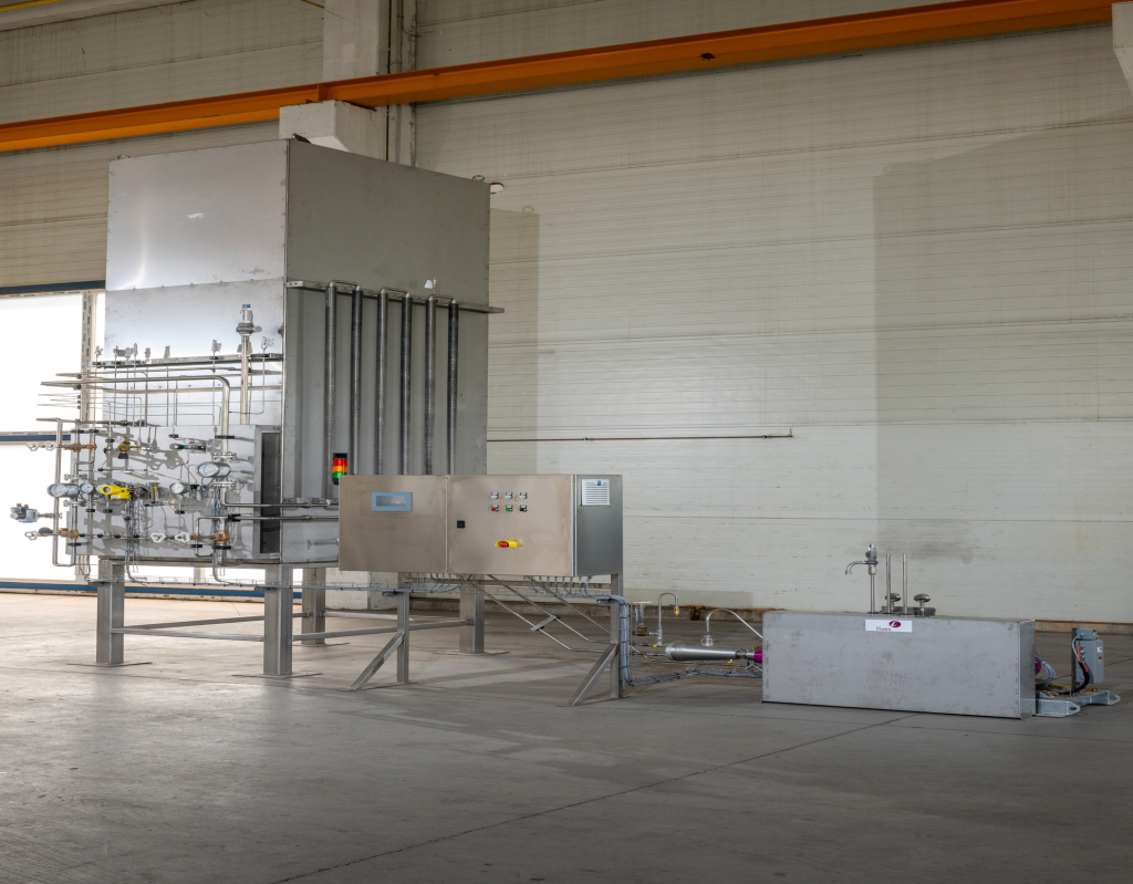
UHP gas delivery system showing cabinet, manifold and piping layout

High Purity and UHP Gas Equipment: Specs and Selection

UHP gas equipment is built to hold specific impurities below 0.1 parts per million, using 316L electropolished stainless steel, controlled surface roughness, orbital-welded or VCR joints, and full batch traceability. High purity equipment sits a step below that, adequate for less critical applications but not for advanced-node process gas. If you are specifying or buying gas delivery equipment for a semiconductor line, the difference between the two is not marketing language. It is the difference between equipment that protects yield and equipment that quietly erodes it.

This guide sets out the specs that actually matter, how to choose the right configuration, and what to check before you sign off on a supplier.

What UHP Actually Means in Numbers

“Ultra-high purity” is not a vague quality claim. It refers to a defined standard: specific impurities held below 0.1 parts per million (ppm) in the gas itself, backed by equipment that will not add contamination back in. In practice, some processes push far beyond that. Advanced 3D NAND fabs, for example, run nitrogen at up to 99.999% purity through volumes reaching 100,000 Nm³ per hour, and next-generation gas analysers using atmospheric pressure ionisation mass spectrometry can now detect impurities down to parts-per-trillion levels for continuous monitoring.

High purity equipment, by contrast, is usually built to a looser tolerance and is common in applications where absolute purity is important but not process-critical. The mistake worth avoiding is assuming the two terms are interchangeable when writing a spec. They are not, and a supplier who does not ask which one you need has not understood the brief.

The Specs That Actually Matter

Material and Grade

316L stainless steel is the standard material for UHP tubing, fittings and panel components, chosen for its resistance to the acids and chlorides common in semiconductor process gases. UHP-grade material is produced with tighter mill-level control over sulphur, phosphorus and metallic inclusions than standard 316L, and this should be confirmed with mill test reports, not taken on trust.

Surface Finish

Internal surface roughness is one of the most commonly under-specified details in a gas system. Most UHP specifications call for an internal surface roughness (Ra) of 10 microinches or less, achieved through electropolishing, an electrochemical process that removes microscopic surface irregularities and improves the stability of the passive oxide layer. Rougher surfaces trap particles and moisture, and both will show up later as contamination events rather than immediate faults, which makes this an easy spec to skip and an expensive one to have skipped.

Joining Method

Orbital-welded joints and VCR face-seal fittings are the two accepted methods for UHP assemblies. Fewer joints generally means fewer leak points, which is why long continuous coiled tubing runs are increasingly preferred over multiple short lengths stitched together on site. Welding procedures should conform to recognised codes such as ASME, with qualified welders and documented procedures, not ad hoc fieldwork.

Testing and Traceability

A UHP assembly should be certified through particle counting, moisture testing and conductivity or cleanliness measurement before it is accepted, and components should arrive cleaned, capped and bagged in a rated cleanroom environment rather than assembled loose on site. Reference standards such as SEMI F20 and ASTM A270 cover these requirements for tubing, and a supplier should be able to point to exactly which standard each component meets, not just say it is “semiconductor grade.”

Choosing the Right Configuration

Getting the material spec right is only half the job. The system architecture around it matters just as much.

Standalone panels versus valve manifold boxes (VMBs). A VMB centralises the switching, monitoring and safety functions for multiple gas sources in one engineered enclosure, and is increasingly the default for fabs handling more than a handful of specialty gases, since it reduces the number of individual connection points and gives a single point of control. JDLL’s UHP gas delivery units are engineered around this kind of centralised, project-specific configuration rather than assembled from generic parts.

Automatic versus manual changeover. Manual changeover is cheaper and simpler, but automatic changeover reduces the risk of a supply interruption during a source swap, which matters more as fabs run closer to continuous production. This is a genuine cost-versus-risk decision and should be made deliberately, not defaulted to whichever option the quote happened to include.

Point-of-use purification. Even a well-specified gas supply picks up trace moisture and airborne molecular contaminants between the source and the tool. Point-of-use purifiers are placed as close to the process chamber as practical to strip out these final traces, and are now considered standard practice on advanced-node lines rather than an optional extra.

Moisture control upstream. Where a gas is generated or conditioned on site rather than delivered pre-purified, gas drying units remove moisture to the specification the downstream process requires, and should be sized to the specific gas type and flow rate rather than fitted as a generic add-on.

What Happens When the Spec Is Wrong, and Why Sourcing Resilience Now Matters Too

Contamination from an under-specified gas system rarely announces itself immediately. It tends to surface later as yield loss, parametric drift, or a reliability failure that is hard to trace back to its source, particularly as device geometries shrink and the acceptable defect margin per process step approaches zero. Getting the spec right at the design stage is far cheaper than diagnosing a contamination excursion after the fact.

2026 has also been a reminder that gas equipment specification is not the only variable. In March 2026, the closure of the Strait of Hormuz following regional conflict disrupted helium exports from Qatar’s Ras Laffan facility, one of the world’s largest helium production hubs, and Qatar had supplied roughly a third of global helium output. Helium is used in semiconductor fabs for leak detection, as an inert carrier gas in deposition, and for wafer cooling during thermal processes, and no substitute gas replicates its combination of inertness, small atomic size and thermal conductivity across those roles. South Korean fabs, which had sourced a large share of their helium from Qatar, were reported to be running down inventory buffers as the disruption continued, while U.S. producers and new capacity in Taiwan offered only partial relief given the scale of Qatar’s former output.

The direct lesson for gas equipment planning is not about helium specifically. It is that supply resilience, not just equipment quality, is now part of the specification conversation. A well-built UHP system fed by a single, undiversified gas source still carries risk. This is one more reason sourcing control and supply chain visibility, not just hardware design, belong in a supplier evaluation, alongside the turnkey engineering and sourcing services a genuine specialty gas partner should offer.

Selection Checklist for a UHP Gas Equipment Supplier

Before signing off on a supplier, confirm:

  • They can state, in writing, which purity grade and which standards (such as SEMI F20 or ASTM A270) each component meets, rather than a general “UHP compliant” claim.
  • Surface finish, material certification and joining method are documented per assembly, with mill test reports and cleanroom packaging evidence available on request.
  • The system is designed around your actual process conditions and KPIs, not selected from a generic catalogue.
  • Automation, monitoring and safety architecture, including SIL-rated safety systems where relevant, are built in from the design stage rather than added afterwards. JDLL’s approach to this is set out on the safety and quality page.
  • The supplier controls or has direct visibility into its own manufacturing and sourcing chain, rather than depending entirely on third-party fabrication with variable quality and lead times.

JDLL has delivered specialty gas systems, including UHP delivery equipment, across 20 countries over the past 25 years, working from its own manufacturing and automation partners rather than outsourced fabrication. More on the company’s background is available on the About JDLL page.

FAQs

What is the difference between high purity and UHP gas equipment?

High purity equipment is built to a looser impurity tolerance and suits applications where cleanliness matters but is not process-critical. UHP (ultra-high purity) equipment is built to hold specific impurities below 0.1 parts per million, using UHP-grade 316L stainless steel, electropolished internal surfaces and full batch traceability, and is required for advanced semiconductor process gas.

Why does surface roughness matter so much in UHP gas systems?

A rough internal surface traps particles and moisture, both of which can be released back into the gas stream during operation. Most UHP specifications require an internal surface roughness of 10 microinches or less, typically achieved through electropolishing, since even a technically pure gas will pick up contamination from a poorly finished delivery system.

Should I choose orbital-welded joints or VCR fittings?

Both are accepted UHP joining methods. Orbital welding suits long, continuous runs where minimising joints is the priority, while VCR face-seal fittings are useful where components need to be removed or serviced without cutting into welded tubing. The right choice depends on the layout of the specific system and how often parts of it will need to be accessed.

What should be included in a UHP equipment acceptance test?

A UHP assembly should be certified through particle counting, moisture testing and conductivity or cleanliness measurement before acceptance, with results documented against the relevant standard. Components should also arrive with mill test reports and evidence of cleanroom packaging, not just a general compliance statement.

Does gas supply disruption affect UHP equipment selection?

Yes. Equipment quality only protects part of the process. If a critical gas such as helium becomes constrained, as happened in 2026 following the Strait of Hormuz closure and its impact on Qatari helium exports, even a well-specified system depends on the reliability of its supply source. Supply chain visibility and sourcing diversity should be part of the same evaluation as the hardware spec itself.


Specifying UHP gas equipment correctly, and choosing a supplier who can prove they meet that spec rather than simply claim it, is what protects yield over the life of a system. Contact JDLL’s engineering team to talk through your specification.

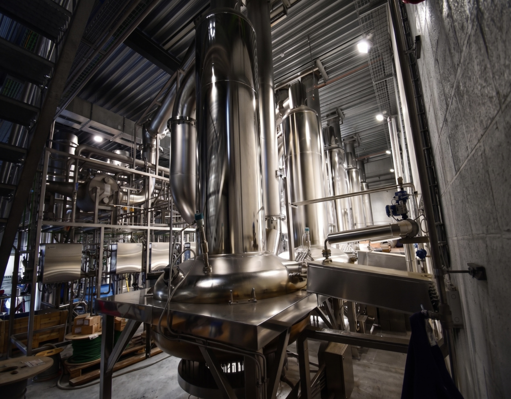
Interior view of stainless steel process columns and piping in a specialty gas purification plant

Nitrous Oxide Plants: How Generation and Supply Work

Nitrous oxide plants generate N2O by thermally decomposing ammonium nitrate at around 250°C, then purifying the resulting gas through scrubbing, moisture removal, compression and drying to reach the purity grade the end use requires. For semiconductor manufacturing, that purity requirement is strict, typically 99.999% (5N) or higher, since N2O is a direct process gas in chemical vapour deposition and any trace contamination can damage the wafer surface it is meant to protect.

This guide covers how generation actually works, why purity grades matter, and what to weigh up between on-site generation and delivered supply.

How Generation Actually Works

Nitrous oxide is produced by heating ammonium nitrate to around 250°C, where it decomposes into nitrous oxide and water vapour through the reaction NH4NO3 → 2H2O + N2O. This thermal decomposition is the standard commercial method for producing N2O at scale, whether the output is destined for food, medical or electronic-grade use.

The raw decomposition reaction does not produce clean gas on its own. Ammonia forms as a side product, since ammonium nitrate is a salt complex rather than a single stable compound, along with trace nitrogen oxides and other impurities. Getting from raw decomposition gas to a usable product requires a purification train: scrubbing in a closed-loop absorption tower removes the bulk of these by-products, a moisture separator strips out remaining condensate, and the gas is then compressed, typically through a multi-stage non-lubricated reciprocating compressor, before final drying removes residual water vapour. Higher purity grades often add a further distillation or cryogenic rectification step to reach electronic-grade specification.

JDLL’s nitrous oxide (N2O) plants are engineered around this full generation and purification chain as a single integrated system, rather than treating purification as an add-on to a basic decomposition unit, since the purification stages are what actually determine whether the output gas meets the purity the customer needs.

Purity Grades and Why the Difference Actually Matters

N2O is produced across a range of purity grades depending on its end use. Food and medical-grade nitrous oxide typically runs at 99.9% purity or above, sufficient for its intended applications. Electronic-grade nitrous oxide for semiconductor use needs to reach 99.999% (5N) or, for some processes, 99.9999% (6N).

The reason this matters is not just a numbers exercise. Even at 5N purity, trace ammonia can still be present at levels between roughly 30 parts per billion and 2 parts per million, and ammonia is specifically damaging to semiconductor surface material. This is why impurity detection, using techniques such as gas chromatography and chemiluminescence-based ammonia analysis, is treated as a critical, ongoing quality control step in electronic-grade N2O production, not a one-off test at the end of the line. A plant that hits the headline purity number on paper but does not actively monitor for trace ammonia and other contaminants throughout production is not actually delivering what a fab needs.

What N2O Is Actually Used For in the Fab

In semiconductor manufacturing, nitrous oxide serves as the main oxygen source for silicon oxide formation during chemical vapour deposition (CVD). It is used to grow high-quality dielectric films, including silicon oxide and silicon oxynitride, that function as insulating layers in integrated circuits and microprocessors, and its role has extended into thin-film oxide processes involving other elements such as titanium and aluminium as device architectures have become more complex. N2O is also used in chamber cleaning steps within CVD tools.

This is a chemically demanding role. The gas needs to support precise, repeatable oxidation reactions at the exact purity level the process was qualified against, since any variation between batches can show up as inconsistent film quality across wafers, not just a single defect.

On-Site Generation Versus Delivered Supply

Fabs generally have two options for sourcing N2O: delivered supply from an external gas producer, or an on-site generation plant integrated into the facility.

On-site generation reduces dependency on cylinder or bulk delivery logistics, cuts handling risk associated with transporting a reactive gas, and gives the fab direct control over purity and supply continuity rather than relying entirely on a supplier’s own production schedule and logistics network. This becomes more significant as fab capacity expands. A facility running at higher throughput needs a correspondingly reliable N2O supply, and a plant sized and engineered for the specific facility’s demand profile avoids the risk of being caught short by a supplier’s allocation decisions during a period of high industry demand.

The trade-off is that on-site generation is a capital commitment that needs to be engineered correctly from the start, since retrofitting a badly specified plant is far more disruptive than getting the design right the first time. This is where JDLL’s turnkey engineering services come in, sizing and designing the generation and purification train around the fab’s actual purity and throughput requirements rather than a standard catalogue unit.

Environmental and Regulatory Considerations

Nitrous oxide is not an incidental environmental consideration in semiconductor manufacturing. The US Environmental Protection Agency has confirmed that N2O is used in CVD and other manufacturing processes such as chamber cleaning, and semiconductor facilities emitting over 25,000 metric tons of CO2-equivalent annually are required to report emissions under the EPA’s Greenhouse Gas Reporting Program for the electronics manufacturing sector. Nitrous oxide is also one of the most significant greenhouse gases emitted by the semiconductor industry specifically, alongside fluorinated compounds such as nitrogen trifluoride and perfluorocarbons.

Industry attention on this has increased. SEMI’s Semiconductor Climate Consortium published a dedicated report in 2025 on abatement technologies for both fluorinated greenhouse gases and nitrous oxide emissions from semiconductor manufacturing, part of a broader industry push toward standardised emissions reporting and reduction targets aligned with the Paris Agreement. For any fab operating or planning an N2O plant, this makes exhaust treatment and gas reclaim a design consideration from day one rather than a retrofit exercise. Vent recovery systems capture and treat unconsumed gas and by-products rather than releasing them, which is increasingly a compliance requirement as much as a cost-control measure.

Checklist for Choosing an N2O Plant Partner

Before committing to a supplier for an on-site nitrous oxide plant, confirm:

  • The purification train is designed to hit and consistently maintain the specific purity grade your process requires, not just a headline percentage on a datasheet.
  • Ongoing impurity monitoring, particularly for trace ammonia, is built into the operating process, not treated as a one-off qualification test.
  • The plant is sized to your actual throughput and future capacity needs, not a standard unit resized after the fact.
  • Vent recovery and exhaust treatment are part of the original design, given the emissions reporting and abatement expectations now common across the industry.
  • Safety and quality documentation, covering material handling, decomposition process controls and commissioning validation, is available from day one of operation.

JDLL applies safety and quality standards consistently across its specialty gas projects, and more on the company’s engineering background is available on the About JDLL page.

FAQs

How is nitrous oxide actually produced?

Nitrous oxide is produced by thermally decomposing ammonium nitrate at approximately 250°C, following the reaction NH4NO3 → 2H2O + N2O. The raw gas from this reaction contains ammonia and other impurities as by-products, so it goes through a purification train, scrubbing, moisture removal, compression and drying, to reach a usable purity grade.

What purity grade of nitrous oxide does semiconductor manufacturing need?

Semiconductor manufacturing generally requires electronic-grade nitrous oxide at 99.999% purity (5N) or higher, compared with the 99.9% purity typical of food or medical-grade N2O. This higher purity is needed because N2O is used directly as a process gas in chemical vapour deposition, where trace contaminants can affect film quality and device yield.

Why is trace ammonia a concern in electronic-grade nitrous oxide?

Ammonia forms as a natural by-product of ammonium nitrate decomposition, and even in high-purity N2O it can remain present at levels between roughly 30 parts per billion and 2 parts per million. Ammonia is specifically damaging to semiconductor surface material, which is why ongoing impurity monitoring for ammonia, not just a final purity check, is a standard part of quality control in electronic-grade N2O production.

What is nitrous oxide actually used for in semiconductor fabrication?

Nitrous oxide serves as the primary oxygen source in chemical vapour deposition, used to grow silicon oxide and silicon oxynitride dielectric films that function as insulating layers in integrated circuits. It is also used in some chamber cleaning steps within CVD process tools.

Should a fab generate nitrous oxide on site or rely on delivered supply?

On-site generation gives a fab direct control over purity and supply continuity, and reduces the logistics and handling risk associated with delivered cylinders or bulk transport, but it requires the plant to be properly sized and engineered for the facility’s actual throughput from the outset. Delivered supply avoids the upfront capital commitment but ties supply reliability to an external producer’s own production and allocation decisions, which becomes a bigger risk during periods of high industry demand.

Are there environmental regulations that apply to nitrous oxide use in semiconductor manufacturing?

Yes. Nitrous oxide is one of the significant greenhouse gases associated with semiconductor manufacturing, and large facilities are required to report emissions under frameworks such as the US EPA’s Greenhouse Gas Reporting Program. The semiconductor industry, through bodies such as SEMI’s Semiconductor Climate Consortium, has also increased focus on abatement technologies for N2O and related emissions, making vent recovery and exhaust treatment a standard design consideration for new N2O plants rather than an optional extra.


Getting an N2O plant right means engineering the full generation and purification chain around your specific purity and throughput needs, not assembling a standard unit and hoping it holds up under real production conditions. Contact JDLL’s engineering team to talk through your nitrous oxide supply requirements.

Semiconductor Gas Equipment: The Complete Guide to Systems, Purity, and Supply

Semiconductor gas equipment is the network of systems, plants and hardware that store, generate, purify, deliver and reclaim the gases used in chip manufacturing. It spans ultra-high-purity (UHP) delivery cabinets and valve manifold boxes, specialty gas generation plants such as nitrous oxide (N₂O) and fluorine (F₂) plants, drying units, vent recovery systems, filling systems and liquefiers. Every one of these systems exists for one reason: a single part per billion of contamination can ruin a wafer batch. Get the equipment wrong and yield, safety and compliance all suffer at once.

This guide walks through what the equipment does, why purity is non-negotiable, what is happening in the supply chain right now, and what to look for in a supplier.

What Semiconductor Gas Equipment Actually Covers

Fabs use two broad categories of gas: bulk gases (nitrogen, oxygen, argon) supplied in large volume for purging and general process use, and specialty or electronic gases (silane, ammonia, nitrogen trifluoride, fluorine and others) used directly in deposition, etching and chamber cleaning steps.

“Semiconductor gas equipment” refers to the hardware layer that sits around both categories: the plants that produce or condition the gas, the panels and manifolds that route it, and the recovery systems that handle what comes out the other end. It is not one product. It is a chain of engineered systems that has to work together without a single weak link, since gas purity, pressure stability and safety interlocks all depend on the whole chain, not just one component.

Core System Types

Ultra-High-Purity (UHP) Gas Delivery Systems

UHP systems control the gases used closest to the process chamber. They combine gas cabinets, purifiers, mass flow controllers and valve manifold boxes (VMBs) to hold contamination at parts-per-billion levels while switching cylinders or sources without interrupting supply. JDLL’s UHP gas delivery units are engineered around project-specific purity and yield targets rather than built to a catalogue spec, since off-the-shelf panels rarely meet the tolerances that leading-edge nodes require.

Specialty Gas Generation Plants

Some gases are more practical to generate on site than to ship in. Nitrous oxide plants and fluorine plants are two examples where on-site generation reduces handling risk and improves supply reliability. JDLL’s nitrous oxide (N₂O) plants and fluorine (F₂) plants are built to hold tight purity and output consistency, since both gases are process-critical and both carry serious handling requirements.

Gas Drying Units

Moisture is one of the most common contaminants in a gas stream, and even trace moisture can affect film quality in deposition and etch steps. Gas drying units remove moisture to the specification the process requires, and are usually sized and configured around the specific gas type and flow rate of the plant they serve.

Vent Recovery Systems

Not all process gas is consumed. What is left over, along with by-products, needs to be captured, treated or reclaimed rather than released. Vent recovery systems reduce waste and environmental exposure while, in the right configuration, recovering gas that would otherwise be lost. This has become a bigger part of procurement conversations as fabs face pressure to cut both cost and emissions at the same time.

Filling Systems

Cylinders, ISO tanks and other containers need to be filled accurately and safely, with the right pressure, purity checks and containment in place. Filling systems are the link between gas production and gas distribution, and their reliability affects everything downstream of them.

Liquefiers

Some specialty gases are stored and transported in liquid form for density and handling reasons. Liquefiers convert gas to liquid under controlled conditions, and are typically paired with the storage and filling infrastructure around them.

Why Purity Is the Whole Point

Every system above exists to protect one thing: process purity. Contamination in a specialty gas stream, whether it is moisture, particulates or trace oxygen, can show up as yield loss, device failure or an entire lot being scrapped. This is why “off-the-shelf” gas plants are rarely a good fit for top-tier manufacturers. A standard panel might handle standard purity requirements, but advanced nodes and tighter process windows mean purity, flow stability and contamination control all need to be engineered to the specific tool and process, not assumed from a catalogue.

This is also why equipment design has shifted from standalone hardware toward integrated systems that combine leak detection, pressure control, flow regulation and continuous monitoring in one package. Buyers increasingly want proof, not just promises, that purity and safety parameters are being held in real time.

The 2026 Supply and Demand Picture

Gas equipment procurement does not happen in a vacuum. It follows fab investment, and fab investment is currently on a historic run.

SEMI’s April 2026 300mm Fab Outlook projects worldwide 300mm fab equipment spending will rise 18% to US$133 billion in 2026 and a further 14% to US$151 billion in 2027, the first time the industry has crossed US$150 billion in a single year. SEMI attributes this to surging AI chip demand and a broader push toward regional semiconductor self-sufficiency, with spending expected to keep climbing through 2029. Memory, particularly high-bandwidth memory for AI training and inference, is a major driver within that number.

That scale of investment turns gas infrastructure into a repeatable facility package rather than a one-off purchase, and it is visible at country level too. Singapore, where JDLL is headquartered, has seen some of the clearest examples: Micron broke ground in January 2026 on a US$24 billion wafer fabrication facility, its largest single investment in the country to date, while VIS Silicon Manufacturing Corporation (VSMC) broke ground on its first 300mm fab in Singapore in late 2024, with production due from 2027. Singapore’s Budget 2026 also committed S$800 million to semiconductor research and development under the government’s RIE2030 plan, on top of a broader S$37 billion technology investment programme announced in late 2025. Regionally, industrial gas majors are moving in step with this build-out: Air Products was selected in April 2026 to supply industrial gases for Samsung Electronics’ next-generation fab in Pyeongtaek, South Korea.

The practical effect for anyone specifying or buying gas equipment right now: lead times are under pressure, supply chains that rely on outsourced or fragmented fabrication carry more risk than they used to, and the gap between suppliers who control their own manufacturing and sourcing and those who do not is becoming more visible. This is part of why JDLL runs its own manufacturing and sourcing hub in Hungary rather than outsourcing fabrication, and why material integrity and supply chain control are treated as a core service, not an afterthought.

Automation, Safety and Compliance

Modern gas equipment is judged as much on its control and safety architecture as on its process performance. Centralised SCADA systems, mobile HMI operation and safety designs built to SIL requirements are now standard expectations on any serious specialty gas project, not premium add-ons. The goal is full operational transparency: audit trails, continuous validation of critical parameters, and safety systems that catch a problem before it becomes an incident rather than after.

Compliance sits alongside this. Gas piping, isolation, leak control and exhaust handling are all areas where buyers expect documentation up front, referencing standards such as SEMI S2 for equipment environmental, health and safety assessment. A supplier who cannot produce this documentation early in a project is a supplier who will slow the project down later.

Choosing a Semiconductor Gas Equipment Partner

A few questions separate a genuine turnkey partner from a hardware vendor:

  • Do they design custom systems around your process KPIs, or resell standard panels?
  • Do they control their own manufacturing and sourcing, or depend on third-party fabrication with variable quality?
  • Is automation and safety architecture integrated from the design stage, or bolted on afterwards?
  • What does after-sales support actually look like once the system is running, not just at handover?

JDLL has completed more than 50 specialty gas projects over the past decade, with equipment now operating across 20 countries, and works from safety and quality standards that are applied consistently across every project regardless of scale. You can read more about the company’s approach on the About JDLL page.

FAQs

What is the difference between bulk gas equipment and specialty gas equipment?

Bulk gas equipment handles large volumes of gases like nitrogen, oxygen and argon for general purging and process support, usually with less stringent purity requirements. Specialty gas equipment handles the smaller-volume, high-purity gases used directly in deposition, etching and cleaning steps, where contamination tolerances are far tighter and the consequences of a failure are more severe.

How is gas purity measured and specified in semiconductor manufacturing?

Purity is typically specified in parts per million or parts per billion for specific contaminants such as moisture, oxygen and particulates, depending on the gas and the process step it feeds. The tighter the process node, the tighter the tolerance usually needs to be, which is why purity specifications are set at the project level rather than taken from a generic product datasheet.

Why are lead times for specialty gas equipment currently under pressure?

Global fab equipment investment is at a historic high, with SEMI projecting worldwide 300mm fab equipment spending to exceed US$150 billion in 2027 for the first time. That level of demand is pulling on the same manufacturing capacity, skilled labour and raw material supply that gas equipment depends on, which is stretching lead times industry-wide, particularly for suppliers without their own manufacturing base.

Can standard gas panels be used instead of custom-engineered systems?

Standard panels can work for lower-purity or lower-criticality applications, but top-tier semiconductor manufacturers generally need custom-engineered systems to hit specific yield, throughput and purity targets. A standard panel is built to a general specification. A custom system is built around the actual operating conditions of a specific fab and process.

What safety standards apply to semiconductor gas systems?

Semiconductor gas systems are generally expected to meet SEMI’s environmental, health and safety guidelines (including SEMI S2) alongside relevant national gas piping and industrial safety codes. Buyers should expect documentation covering gas isolation, leak control, exhaust handling and functional safety (SIL) ratings before site acceptance.

How do vent recovery systems help with environmental compliance?

Vent recovery systems capture and treat gas and by-products that are not consumed in the process, reducing what is released to atmosphere and, in some configurations, recovering gas for reuse. This supports both environmental compliance and cost control, since less gas is wasted and less needs to be treated as pure exhaust.


Specifying the right combination of UHP delivery, generation plants, drying, recovery, filling and liquefaction takes more than a product catalogue. It takes a partner who designs around your actual process conditions and controls their own supply chain end to end. Get in touch with JDLL’s engineering team to talk through your project.

Engineers conducting an on-site installation and commissioning check on an industrial gas plant

Industrial Gas Plant Design, Installation, and Maintenance

Industrial gas plant design, installation, and maintenance work as one continuous lifecycle, not three separate contracts. A design that ignores installation realities creates rework on site. An installation that skips proper commissioning creates safety and reliability gaps that surface months later. Maintenance planned as an afterthought turns into reactive firefighting instead of predictable uptime. The plants that perform well over their operating life are the ones where all three phases were planned together from day one, usually by the same engineering team.

This guide covers what each phase actually requires and what to check before handing any of them to a contractor.

Design: Getting the Process Right Before Anything Is Built

Gas plant design starts with the process itself, not the equipment catalogue. Every specialty gas system, whether it is a nitrous oxide plant, a fluorine plant, a UHP delivery system or a vent recovery unit, needs its purity targets, throughput requirements and safety parameters defined against the actual operating conditions it will face, not generic assumptions.

This is also where hazard analysis happens. A structured HAZOP (Hazard and Operability Study) identifies process deviations and their consequences, and feeds into a Layer of Protection Analysis (LOPA) that determines what safety instrumented functions are needed and at what Safety Integrity Level (SIL). This SIL determination process is governed internationally by IEC 61511, the process industry adaptation of the broader IEC 61508 functional safety standard, with ANSI/ISA 84 as its US equivalent. IEC 61511 covers the entire lifecycle of a safety instrumented system, from hazard analysis and design through installation, commissioning, operation and maintenance, which is exactly why safety cannot be bolted on after a plant is designed. It has to be part of the design brief itself.

Material selection is decided here too. Gas type, purity requirement and corrosion risk all dictate whether standard stainless steel is adequate or whether the application calls for electropolished UHP-grade material and specific joining methods. JDLL’s UHP gas delivery units and nitrous oxide (N₂O) plants are both designed around these project-specific decisions rather than built from a standard template, since a plant designed to a generic spec rarely performs to a specific one.

Installation: Where Design Either Holds Up or Falls Apart

A well-designed plant can still fail on site if installation is treated as a separate, disconnected phase. Good installation practice starts with factory acceptance testing (FAT), where the system is assembled and tested under controlled conditions before it ever reaches site, catching design or fabrication issues while they are still cheap to fix.

Site acceptance testing (SAT) follows once the plant is installed, verifying that it performs correctly in its actual operating environment, not just the factory floor. This is also where the safety instrumented systems designed earlier are commissioned and validated, since IEC 61511 requires installation and commissioning to be treated as part of the same safety lifecycle as the original hazard analysis, not a separate exercise carried out by a different team with no visibility into the original design intent.

Documentation matters as much as the physical build during this phase. Buyers should expect full traceability: material certificates, weld records, pressure test results and safety validation reports, all handed over at commissioning rather than assembled retroactively when an auditor asks for them. JDLL’s safety and quality standards are applied consistently through this stage, since a plant that cannot produce this documentation on day one of operation is a plant that will struggle to prove compliance later.

Maintenance: The Phase That Determines the Real Lifetime Cost

Maintenance strategy is usually where the biggest gap appears between a plant’s theoretical performance and what it actually delivers over 10 or 20 years of operation.

Reactive maintenance, fixing things after they fail, is the most expensive approach and the most disruptive, since failures in gas systems can mean scrapped product, safety incidents or unplanned shutdowns. Preventive maintenance on a fixed schedule is better, but it services equipment whether or not it actually needs it, wasting effort on healthy components while sometimes still missing a developing fault between scheduled checks.

Predictive maintenance, using condition monitoring data such as vibration, pressure and flow trends to schedule interventions only when a component actually shows early signs of wear, has moved from a research project to standard practice across process industries. According to Deloitte Insights, predictive maintenance can increase equipment uptime and availability by 10 to 20% and reduce overall maintenance costs by 5 to 10% compared with reactive or purely calendar-based approaches. For gas plants specifically, this kind of continuous monitoring is a natural extension of the SCADA and automation systems already built into the plant during design, rather than a separate system bolted on afterwards.

After-sales support is the other half of this phase, and it is where many buyers discover the difference between a hardware vendor and a genuine long-term partner. Facility downtime during a gas supply issue is expensive by the minute, and support that routes through a general call centre with no direct line to the engineers who built the system adds delay at exactly the point it matters least. JDLL’s approach to services is built around 24/7 multilingual support and direct access to the team that engineered the plant, specifically because generic support desks are one of the most common complaints buyers raise about large multinational suppliers.

Why 2026 Is Putting Pressure on All Three Phases at Once

Design, installation and maintenance capacity are all being stretched by the same underlying trend: a historic wave of fab investment. SEMI’s April 2026 300mm Fab Outlook projects worldwide 300mm fab equipment spending will rise 18% to US$133 billion in 2026 and 14% to US$151 billion in 2027, the first time the industry has crossed US$150 billion in a single year, driven by AI chip demand and a broader push toward regional semiconductor self-sufficiency.

Singapore is a direct example of what that means on the ground. Micron broke ground in January 2026 on a US$24 billion wafer fabrication facility, and VIS Silicon Manufacturing Corporation (VSMC) broke ground on its first 300mm fab in Singapore in late 2024, with production due from 2027. Each of these projects needs gas infrastructure designed, installed and commissioned on a timeline set by the broader fab construction schedule, which puts real pressure on engineering and installation capacity across the region, not just on equipment lead times.

The practical implication: a design-and-install partner without spare engineering capacity or without control over their own fabrication and sourcing is more likely to slip on schedule right now than they would have been two or three years ago. This is part of why JDLL runs its own manufacturing and automation partners in Hungary rather than depending entirely on third-party fabrication, a point covered in more detail on the About JDLL page.

Checklist for Evaluating a Design, Installation, and Maintenance Partner

Before committing to a supplier for the full lifecycle, confirm:

  • Design decisions (material, SIL rating, purity targets) are documented against your actual process conditions, not assumed from a standard template.
  • FAT and SAT are both standard practice, not optional extras that get skipped under schedule pressure.
  • Full documentation, material certificates, weld records, safety validation, is handed over at commissioning, not assembled after the fact.
  • Maintenance strategy includes condition monitoring and predictive scheduling, not just a fixed preventive maintenance calendar.
  • After-sales support gives direct access to the engineers who built the system, with support available outside standard office hours.

FAQs

Why should design, installation, and maintenance be handled by the same partner?

Each phase depends on decisions made in the one before it. A design team that never sees how their plant is actually installed and maintained cannot learn from that feedback, and an installation or maintenance team with no visibility into the original design intent is working with less context than they need. A single accountable partner closes that gap and reduces the risk of issues falling between contractors.

What is FAT and SAT in gas plant installation?

Factory Acceptance Testing (FAT) verifies that a system performs correctly under controlled conditions before it leaves the factory, catching design or fabrication issues while they are still inexpensive to fix. Site Acceptance Testing (SAT) verifies the same system once it is installed in its actual operating environment, confirming it performs correctly on site, not just on the factory floor.

What is SIL and why does it matter for gas plant design?

SIL (Safety Integrity Level) is a rating, from 1 to 4, that defines how much risk reduction a safety instrumented function needs to provide, determined through hazard analysis methods such as HAZOP and LOPA under the IEC 61511 standard. It matters because it sets the actual safety requirements a gas plant’s control and shutdown systems must meet, rather than leaving safety design to general good practice alone.

What is the difference between preventive and predictive maintenance?

Preventive maintenance services equipment on a fixed schedule regardless of its actual condition, which can waste effort on healthy components while still missing faults that develop between scheduled checks. Predictive maintenance uses condition monitoring data, such as vibration, pressure or flow trends, to schedule interventions only when a component shows early signs of wear, generally reducing both downtime and overall maintenance cost compared with a purely calendar-based approach.

How does documentation affect gas plant compliance?

Regulators, auditors and insurers generally expect full traceability for a gas plant: material certificates, weld records, pressure test results and safety validation reports. If this documentation is assembled retroactively rather than captured during design and installation, it becomes far harder to demonstrate compliance quickly when it is actually requested, which can delay audits, certifications or incident investigations.

Why is gas plant installation capacity currently under pressure globally?

Global fab equipment investment is at a historic high, with SEMI projecting worldwide 300mm fab equipment spending to exceed US$150 billion in 2027 for the first time. That level of investment means more new plants being designed, installed and commissioned on overlapping timelines, which is stretching engineering and installation capacity industry-wide, particularly for suppliers without their own manufacturing base or spare engineering capacity.


A gas plant is only as good as the weakest phase in its lifecycle. Getting the design right and then losing the plot at installation, or getting both right and then treating maintenance as an afterthought, all lead to the same outcome: a plant that underperforms its real potential. Contact JDLL’s engineering team to talk through your project from design through to long-term support.

Scroll to Top